IPTables: Matching A GRE packet based on tunnel key

I was trying to figure out a way to match packets with a certain GRE key and take some action. IPTables does not provide a direct solution to this problem but has the u32 extension modules that can be used to extract 4 bytes of the IP header and match against a pattern.

So, I decided to give a try to this extension.

Prepare the setup

I created a tunnel between 2 of my VMs and assign IP address to the tunnel interfaces

On VM1

sudo ip tunnel add tun2 mode gre remote 192.168.122.103 local 192.168.122.134 ttl 255 key 22

sudo ifconfig tun2 6.5.5.1/24 up

On VM2

sudo ip tunnel add tun2 mode gre remote 192.168.122.134 local 192.168.122.103 ttl 255 key 22

sudo ifconfig tun2 6.5.5.2/24 up

Start with a basic rule

Next, created a IPTables rule on the receiving system to generate logs for packet match, but you can also create an ACCEPT rule and check the builtin packet counter for the rule.

sudo iptables -I INPUT -p 47 -m limit --limit 20/min -j LOG --log-prefix "IPT GRE" --log-level 4

Now start ping from VM2 to VM2

ping 6.5.5.1

You can keep a watch on the packet counters with the following command

watch "sudo iptables -L -v -n"

The GRE header

Next, a look at the GRE header format (taken from RFC https://tools.ietf.org/html/rfc2890). The header format is described in the RFC and it contains an optional 32bit key, which is the data of our interest.

0 1 2 3 4 5 6 7 8 9 0 1 2 3 4 5 6 7 8 9 0 1 2 3 4 5 6 7 8 9 0 1
+-+-+-+-+-+-+-+-+-+-+-+-+-+-+-+-+-+-+-+-+-+-+-+-+-+-+-+-+-+-+-+-+
|C| |K|S| Reserved0       | Ver |         Protocol Type         |
+-+-+-+-+-+-+-+-+-+-+-+-+-+-+-+-+-+-+-+-+-+-+-+-+-+-+-+-+-+-+-+-+
|      Checksum (optional)      |       Reserved1 (Optional)    |
+-+-+-+-+-+-+-+-+-+-+-+-+-+-+-+-+-+-+-+-+-+-+-+-+-+-+-+-+-+-+-+-+
|                         Key (optional)                        |
+-+-+-+-+-+-+-+-+-+-+-+-+-+-+-+-+-+-+-+-+-+-+-+-+-+-+-+-+-+-+-+-+
|                 Sequence Number (Optional)                    |
+-+-+-+-+-+-+-+-+-+-+-+-+-+-+-+-+-+-+-+-+-+-+-+-+-+-+-+-+-+-+-+-+

Run the following tcpdump command to capture the packets(My VMs don’t have GUI)

sudo tcpdump -s 0 -n -i ens3 proto GRE -w dump.pcap

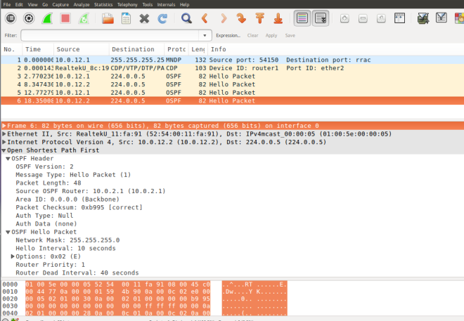
The captured packets can be analyzed using wireshark

untitled1

Understanding the iptables u32 extension match rule

Basically u32 module is able to extract 4 byte of data from the IP header at a given offset and match with the given hex number or range. Here is an example of a u32 match rule from the man-page. It matches packets within a certain length. The man page describes the format of the rule, you provide an offset , u32 extracts 4 byte from the offset position, and then we AND it with the MASK and finally compare with the HEX value

Example:

match IP packets with total length >= 256
The IP header contains a total length field in bytes 2-3.

--u32 "0 & 0xFFFF = 0x100:0xFFFF"

read bytes 0-3
AND that with 0xFFFF (giving bytes 2-3), 
and test whether that is in the range [0x100:0xFFFF]

The man page has more details.

Craft a match for GRE Key

The IP header length is 20 bytes and the GRE key starts at 24 bytes, as can be confirmed from the wireshark. At the beginning of the rule match starts at the IP header(highlighted in the wireshark screenshot)

untitled

Based on the example from the man page I crafted the following rule to match the GRE key.

sudo iptables -I INPUT -p 47 -m u32 --u32 "24 & 0xFFFFFFFF = 0x16" -m limit --limit 20/min -j LOG --log-prefix "IPT GRE key 22" --log-level 4

Checking for Key Present Flag

But the key can be optional. So, add match for Key-Present Flag.

sudo iptables -I INPUT -p 47 -m u32 --u32 "20 & 0x20000000 = 0x20000000 && 24 & 0xFFFFFFFF = 0x16" -m limit --limit 20/min -j LOG --log-prefix "IPT GRE key 22" --log-level 4

Here is a screen capture of the iptables packet counters

Chain INPUT (policy ACCEPT 294K packets, 78M bytes)
 pkts bytes target prot opt in out source destination
 711 79632 LOG 47 -- * * 0.0.0.0/0 0.0.0.0/0 u32 "0x14&0x20000000=0x20000000&&0x18&0xffffffff=0x16" limit: avg 20/min burst 5 LOG flags
 0 level 4 prefix "IPT GRE key 22"

The above rule is simplistic and good to get you started but has short comings, e.g. it assumes a constant IP header length.

The man page describes examples of how to handle variable length headers, fragmentation check etc.

Running a standalone OpenStack Neutron server

One of the great advantage for an OpenStack developer is the ease with which a dev environment can be created. I cannot say enough good things about devstack. Devstack is a tool that provides a very flexible way of creating development environment for OpenStack.

Devstack is very flexible and can be configured using simple config file (local.conf). Another advantage of running devstack based environment is that it hardly needs any special hardware prerequisite. A VM on your laptop is good enough to bring-up an all-in-one OpenStack environment, although a good amount of RAM and CPU for your VM will yield better results.

As a developer interested in OpenStack networking (Neutron) my interest lies mostly on the Neutron service and most of the time I find a lot of OpenStack services are not really required for my day-to-day activity. So I decided to tweak the my devstack config file to start only the minimum services, just enough to run networking service and save a little on my devstack VMs RAM and CPU requirement.

The OpenStack networking service itself depends on the common set of infrastructure services like the database server, rabbitmq etc. The following is the local.conf that I used for this purpose.

[[local|localrc]]
ADMIN_PASSWORD=XXXXXXXXX
DATABASE_PASSWORD=$ADMIN_PASSWORD
RABBIT_PASSWORD=$ADMIN_PASSWORD
SERVICE_PASSWORD=$ADMIN_PASSWORD
 
GIT_BASE=https://git.openstack.org
LOGFILE=/opt/stack/logs/stack.sh.log 
#Q_PLUGIN_EXTRA_CONF_PATH += '/etc/neutron/fwaas_driver.ini'
RECLONE=yes
LIBS_FROM_GIT=python-neutronclient
 
disable_all_services

enable_service rabbit
enable_service database
enable_service mysql
enable_service infra
enable_service keystone
enable_service q-svc
enable_service neutron

With the above local.conf only the network service and basic infrastructure are started by devstack. Here is a list of windows in my screen session

0$ shell  1$(L) key  2$(L) key-access  3$(L) q-svc   4$ code*  5-$ log

The Last two windows are manually created for browsing the code and looking at my custom logs.

Test-driving arbitrary data publishing over BGP

BGP is a routing protocol known for its strength in scaling and resilience. It is also flexible and extensible.  With its Multi-Protocol extension BGP can support distribution of various data types. Still to extend BGP for every new route data type  requires introduction of new address family(AFI/SAFI) and making BGP aware of the new data type.

What if we could just distribute any arbitrary data over BGP without the need for introduction of changes to BGP? Of-course the BGP end point itself cannot decipher the arbitrary data but the data can be passed on to other applications which can make sense of it.

Well this feature is proposed in the following IETF draft

https://tools.ietf.org/html/draft-lapukhov-bgp-opaque-signaling-02

The draft proposes introduction of a generic opaque Address family to allow distributing arbitrary key value pair over BGP.

Testing opaque data dissemination over BGP

While investigating GoBGP for my previous experiment I realized that GoBGP has support for Key Value based opaque data dissemination. So let’s see how we can disseminate a Key Value pair of arbitrary data over BGP.

For this experiment I am using a simple linear topology as shown below.

slide1

Also I have used mininet to simulate the above topology using Linux Network Name Spaces as the BGP speakers.

Starting the topology

Install mininet using apt-get commands as follows

$ sudo apt-get install mininet

Start the default linier topology as follows. This topology has two hosts H1(10.0.0.1) and H2 (10.0.0.2) connected through a switch

$ sudo mn
mininet>

Start GoBGP instances on the hosts. To do this create 2 config files one for each GoBGP instance. The following is an example config file for H1(10.0.0.1).

[global.config]
  as = 64512
  router-id = "10.0.0.1"
[[neighbors]]
[neighbors.config]
  neighbor-address = "10.0.0.2"
  peer-as = 64512
[[neighbors.afi-safis]]
  [neighbors.afi-safis.config]
  afi-safi-name = "opaque"

To start the GoBGP instance use the following command

mininet> h1 ./GO_WA/bin/gobgpd -f ./gobgpd_h1.conf &
mininet> h2 ./GO_WA/bin/gobgpd -f ./gobgpd_h2.conf &

Check the BGP neighbor status

mininet> h1 /home/ubuntu/GO_WA/bin/gobgp nei
Peer        AS  Up/Down State       |#Advertised Received Accepted
10.0.0.2 64512 00:00:24 Establ      |          0        0        0

Also make sure that the neighbor had the capability to publish and consume opaque data

mininet> h1 ./GO_WA/bin/gobgp neigh 10.0.0.2
BGP neighbor is 10.0.0.2, remote AS 64512
  BGP version 4, remote router ID 10.0.0.2
  BGP state = BGP_FSM_ESTABLISHED, up for 1d 05:45:43
  BGP OutQ = 0, Flops = 0
  Hold time is 90, keepalive interval is 30 seconds
  Configured hold time is 90, keepalive interval is 30 seconds
  Neighbor capabilities:
    BGP_CAP_MULTIPROTOCOL:
        opaque: advertised and received
    BGP_CAP_ROUTE_REFRESH:      advertised and received
    BGP_CAP_FOUR_OCTET_AS_NUMBER:       advertised and received
  Message statistics:
                         Sent       Rcvd
    Opens:                  1          1
    Notifications:          0          0
    Updates:                4          0
    Keepalives:          3572       3572
    Route Refesh:           0          0
    Discarded:              0          0
    Total:               3577       3573
  Route statistics:
    Advertised:             3
    Received:               0
    Accepted:               0

Publishing an opaque Key-Value pair

Use the following command to publish any key value pair over BGP connection.

mininet> h1 ./GO_WA/bin/gobgp global rib add key key1 value value1 -a opaque
mininet> h1 ./GO_WA/bin/gobgp global rib add key key2 value value2 -a opaque
mininet> h1 ./GO_WA/bin/gobgp global rib add key key3 value value3 -a opaque

Verify that the opaque data is received on the BGP peers i.e. H2

mininet> h2 ./GO_WA/bin/gobgp global rib -a opaque

  Network Next Hop  Age      Attrs
*>key1    10.0.0.1  00:01:10 [{Origin: ?} {LocalPref: 100} {Value: value1}]
*>key2    10.0.0.1  00:00:09 [{Origin: ?} {LocalPref: 100} {Value: value2}]
*>key3    10.0.0.1  00:00:03 [{Origin: ?} {LocalPref: 100} {Value: value3}]

Conclusion

Publishing arbitrary data over BGP can be used to distribute application specific configuration.  BGP will not try to interpret the opaque data. The data must be used by the application. The draft proposes BGP implementation may provide APIs for the application to publish and consume opaque data.


Test-driving EVPN route publishing with GoBGP

In recent times there has been a lot of interest in tunnel based L2 networks, especially for Cloud Networks implemented with VXLAN.  The tunnel based networks were initially proposed with the idea of alleviating the 4k limit imposed with VLAN based networks.

EVPN based VXLAN tunneled networks use BGP as control plane for L2 learning. In this port we will test GoBGP for publishing L2 routes.

L2 learning in tunneled networks

The tunnel based networks need special handling of L2 learning. L2 learning consists of learning how to reach certain MAC (and IP address) in the network. In a normal VLAN based network this is done using the data path, i.e. when two IP addresses communicate in a VLAN the switch in the data path use the source MAC address of the packet to learn which port of the switch is connected a MAC address. This normally happens during the ARP resolution phase that converts the IP(L3) address to MAC(L2) address. It involves flooding all ports of the switch to query for the MAC address associated with the requested IP address.

In a tunnel based networks each of the endpoint form a full mesh of tunnels with all other endpoints.  Unfortunately, data path learning is a very costly option for tunnel based network as it requires flooding of all the tunnels.

Control Plane based L2 learning

The tunnel based networks instead implement a control plane based L2 learning. The control plane based learning work by proactively publishing the location of a MAC(L2) address on the overlay network to all the tunnel end-points.

To implement a control plane based learning someone with the knowledge of location of the MAC(L2) address on the overlay network must send this information to all the tunnel endpoints. This can be done by using a central controller which has a complete knowledge of the overlay network. This is how SDN controllers work, these controllers have the complete view of the network and can publish L2 reachability information to all tunnel endpoints

The EVPN solution uses a combination of data path and control plane learning. Each tunnel endpoint implements a local data path learning and publishes the learned L2 reachability information as L2 routes to the remote endpoints. It uses BGP to publish local and learn remote L2 addresses.

Publishing a L2 route

The L2 route consist of a MAC address (and optionally the associated IP address) and a next-hop IP address of the VTEP. This essentially means that any endpoint trying to send a packet to a MAC on the overlay network should look up its local L2 route table for the destination MAC and send the encapsulated L2 packet to the next hop VTEP IP.

Publishing L2 routes with GoBGP

Now that we have the theory of L2 route publishing cleared, let’s look at some real example of L2 routes published over BGP.

GoBGP is an open source BGP implementation which supports publishing EVPN routes. The following figure represents the test topology. It consists of three BGP peers connected in full mesh.  The VTEP IPs are used to create the BGP peers.

slide1

The Router details are as Follows(These are KVM instances started using libvirt and use the management IP for router-id)

Device VTEP-IP
Router1 192.168.122.3
Router2 192.168.122.87
Router3 192.168.122.174

To install GoBGP refer to the install documentation available at

https://github.com/osrg/gobgp/blob/master/docs/sources/getting-started.md

We are going to use the following configuration file to start BGP service Router1. Similar configuration files will be used to start the gobgpd instances on the other routers

[global.config]
  as = 64512
  router-id = "192.168.122.3"
[[neighbors]]
[neighbors.config]
  neighbor-address = "192.168.122.87"
  peer-as = 64512
[[neighbors.afi-safis]]
  [neighbors.afi-safis.config]
  afi-safi-name = "l2vpn-evpn"
[[neighbors]]
[neighbors.config]
  neighbor-address = "192.168.122.174"
  peer-as = 64512
[[neighbors.afi-safis]]
  [neighbors.afi-safis.config]
  afi-safi-name = "l2vpn-evpn"

To start the gobgpd instance use the following command

# gobgpd -f gobgpd.conf

gobgp0

Check that all the neighbors have established BGP connection and EVPN route are supported

gobgp1

To publish and view a L2 route use the following commands.

# gobgp global rib add macadv aa:bb:cc:dd:ee:04 2.2.2.4 1 1 rd 64512:10 rt 64512:10 encap vxlan -a evpn
# gobgp global rib -a evpn

Here is an example

Router3 >gobgp global rib add macadv aa:bb:cc:dd:ee:05 2.2.2.5 1 1 rd 64512:10 rt 64512:10 encap vxlan -a evpn
Router3 >gobgp global rib -a evpn
    Network                                                                                            Next Hop             AS_PATH              Age        Attrs
*>  [type:macadv][rd:64512:10][esi:single-homed][etag:1][mac:aa:bb:cc:dd:ee:05][ip:2.2.2.5][labels:[1]]0.0.0.0                                   00:00:02   [{Origin: ?} {Extcomms: [64512:10], [VXLAN]}]

The following screen shout captures the output

gobgp2.png

The above route tells the router to send any L2 packet destined to “aa:bb:cc:dd:ee:05” to the VTEP IP of Router3 over a VXLAN tunnel.

Let’s check that the L2 routes show up on the other Routers. The following route is learned through BGP on Router1.

Router1 >gobgp global rib -a evpn
    Network                                                                                            Next Hop             AS_PATH              Age        Attrs
*>  [type:macadv][rd:64512:10][esi:single-homed][etag:1][mac:aa:bb:cc:dd:ee:05][ip:2.2.2.5][labels:[1]]192.168.122.174                           00:00:38   [{Origin: ?} {LocalPref: 100} {Extcomms: [64512:10], [VXLAN]}]

The following screen shout captures the output

gobgp3

The route says: a  L2 packet destined for “aa:bb:cc:dd:ee:05” should be encapsulated as in  VXLAN tunnel and sent to  192.168.122.174(the VTEP IP of Router3).

Conclusion

From the above demonstration is can be seen how BGP based control plane is used by EVPN to distribute the L2 routes. This approach removes the need for a centralized controller which can become a single point of failure and bottleneck while scaling overlay networks


A simple metadata server to run cloud images on standalone libvirt :: KVM Hypervisor

With all the interest in Cloud Computing and virtualization, the OS vendors are providing ever more easier ways to deploy VMs. Most of them now come with cloud images. This makes it really easy for users to deploy VMs with the distro of their choice on a cloud platform like OpenStack or AWS.

Here are a few mentions of the available cloud images

https://cloud-images.ubuntu.com/

https://getfedora.org/en/cloud/download/

http://cloud.centos.org/centos/

Complete Lock-down

But, what about users wanting to deploy virtual machines on standalone Hypervisors? With so many pre-built images available, why should anyone need to install virtual machines from scratch?

With this thought in mind I decided to give these cloud images a try on my Hypervisor. I use libvirt with KVM on a physical server as my Hypervisor.

I realized quickly that these images are completely locked down, there is no default password, no web interface and most of then are configured with serial console.

Auto configuration deamon

These VM images are configured with a configuration daemon called cloudinit. When these cloud image based VM boots for the first time the cloudinit daemon tries to retrieve configuration information from various data sources and sets up things like password for the default user, hostname, SSH keys etc. A complete manual of cloudinit is available here

The cloudinit daemon can retrieve these configuration settings from sources like a ConfigDrives, CDROM attached to the VM(NoCloud) or from the network(EC2).

A Simple Solution

In my previous attempts to use a cloud image I followed the CDROM (attached ISO) based approach to provide the configuration data to the VMs. This quickly gets very cumbersome.

So the obvious thought was to try to mimic the metadata service provides by the cloud platform. The metadata service is a web service that provides the configuration data to the cloud images. As the cloud images boot, they send a DHCP request to get an IP address, then it contacts the metadata service on the network and try to retrieve the configuration for the VM. The metadata service is expected to be available at the well-known IP address of 169.254.169.254.

The libvirt configuration provides a default network to the VMs. It also provides a DHCP service to allocate IP to the VMs from a subnet pool of 192.168.122.0/24. All the VMs connect to the default network bridge; virbr0. This bridge also acts at the network Gateway and is configured with the IP 192.168.122.1. The topology is shown in the image below.

Slide1

With some trial and error I could come up with a Simple Metadata Service that can be used on a standalone libvirt/KVM based hypervisor to support booting cloud images. The metadata service is a python bottle app and you will need to install bottle web framework.

# pip install bottle

To make the metadata service work add the metadata IP to the bridge interface as follows:

 # ip addr add 169.254.169.254 dev virbr0

Download the server code from

https://bitbucket.org/xchandan/md_server

Build and Install the mdserver package

# python setup.py bdist_rpm 
# rpm -ivh dist/mdserver-<version>.noarch.rpm

or

# python setup.py install

Then start the metadata server as follows

# systemctl start mdserver

or

# mdserver /etc/mdserver/mdserver.conf

Setting password and ssh-key

You can set the password and ssh public key using the /etc/mdserver/mdserver.conf file. An example cam be found here (md_server/etc/mdserver/mdserver.conf.test in the source tree)

[mdserver]
password = password-test

[public-keys]
default = ssh-rsa ....

Note: The Hostname of the VM is set to the libvirt domain name. Although the mdserver can be run on ports other then 80, this is only for testing, the cloud images will always contact 169.254.169.254 on port 80 for metadata

With the metadata server running you should be able to start VMs with cloud images.

The simple metadata service is able to set the hostname, password for the default user, set SSH authorized key and enables password based SSH access.

I was able to test it with cirros, Ubuntu and Fedora images.


Test-Driving OSPF on RouterOS – Interoperability

So I wrote about OSPF on RouterOS in my previous post. It was a nice experiment to learn about routing protocols.

I wanted to take it a little further and test Interoperability of RouterOS with other open source solutions.

This post is an update from the previous one and I will add OSPF neighbor nodes to the setup. I decided to use Quagga the most talked about open-source routing protocol suit and XORP the eXtensible Open Router Platform.

Updated Setup

The following is the updated setup for the Interoperability test. I have added two new Ubuntu nodes as OSPF neighbor.

  • Quagga on Ubuntu
  • XORP on Ubuntu

Slide3.jpg

Configuration

Quagga

The following configuration was added to Quagga node

Screenshot from 2016-03-27 12:33:55.png

XORP

The XORP node did not advertise any new subnet but received OSPF updates.

XORP_Conf.png

Results

  • All the nodes could discover their neighbors

Screenshot from 2016-03-27 00:03:27.png

  • All nodes got route updates.

Screenshot from 2016-03-27 01:54:34.png

  • OSPF Traces

Screenshot from 2016-03-27 01:57:34.png

Test-driving OSPF on RouterOS

I came across RouterOS by MikroTik© which provides advances routing protocol support. What is more amazing is they provide a RouterOS in a virtual form-factor called Cloud Hosted Router (CHR) that can be installed on hypervisors like KVM/VirtualBox/VMware.

Please look at licensing model at http://wiki.mikrotik.com/wiki/Manual:CHR#CHR_Licensing

This is perfect for learning purposes and experimenting at home. So I decided to test OSPF routing with Router OS.

The Setup

The following diagram describes my network setup. All for these are installed as VMs on my home desktop. Slide2

The footprint of the router VMs are quite small. MikroTik© recommends 128 MB RAM and 128 MB of HDD as minimal hardware requirements. I used virt-manager to setup the test network. Here is a typical VM configuration.

The actual setup however needs some hosts on the network to test the connectivity after implementing OSPF. To keep things lite weight I used NameSpaces to simulate hosts connected to the routers. Linux bridges were used to connect the routers and the hosts. The following figures show the final setup. Slide1

OSPF Configuration

For testing purpose I restricted my setup to area 0 to which both routers are connected. Following configuration is used on the routers.

Router1

/routing ospf instance
set [ find default=yes ] router-id=10.0.1.1
/ip address
add address=192.168.122.101/24 interface=ether1 network=192.168.122.0
add address=10.0.12.1/24 interface=ether2 network=10.0.12.0
add address=10.0.1.1 interface=loopback network=10.0.1.1
add address=10.10.0.1/24 interface=ether4 network=10.10.0.0
/routing ospf network
add area=backbone network=10.0.12.0/24
add area=backbone network=10.10.0.0/24
/system identity
set name=router1
[admin@router1] >

Router2

/routing ospf instance
set [ find default=yes ] router-id=10.0.2.1
/ip address
add address=192.168.122.102/24 interface=ether1 network=192.168.122.0
add address=10.0.12.2/24 interface=ether3 network=10.0.12.0
add address=10.20.0.1/24 interface=ether4 network=10.20.0.0
add address=10.0.2.1 interface=loopback network=10.0.2.1
/routing ospf network
add area=backbone network=10.0.12.0/24
add area=backbone network=10.20.0.0/24
/system identity
set name=router2
[admin@router2] >

Config-1

Results

I was able to get OSPF running with RouterOS in no time. Here are the test results.

  • Routing tables on the routers

OSPF-route

  • Routing tables on the hosts

HOST-route

  • Ping tests

PING

  • OSPF Traces

OSPF-ROS