Connecting my Dev VM to GCP: Test driving sshuttle

I have been working on a project which requires me to connect to my test environment deployed on GCP. We don’t have public IPs available for all the VMs in the test environment, but one of the VMs in the deployment is configured as a JumpHost i.e it has a public IP available. We need to jump through this VM to get to any other VMs in the test environment.

This is quite a standard setup for many companies who deploy software on cloud computes. It helps us to protect the test VMs from getting exposed to the external world thereby reducing the attack surface and also Public IPs are not necessary for the tests we run in  our environment.

SSh client JumpHost configuration

Normally it’s just fine to configure your ssh client to connect to the VMs not having the public IPs using a JumpHost configuration. Quoting directly from Gentoo wiki

### First jumphost. Directly reachable
Host betajump
  HostName jumphost1.example.org
 
### Host to jump to via jumphost1.example.org
Host behindbeta
  HostName behindbeta.example.org
  ProxyJump  betajump

The issue we have is these VMs often gets re-deployed with dynamic IPs.  This makes the ssh client configuration invalide after each deployment.

Site-to-Site Cloud VPN

We can of course use a cloud VPN to get access to these VM with private IPs but getting access to Public IP in the office network is beyond my current role 🙂 . Although there are a lot of discussion happening about the shiny new VPN just got included in the linux Kernel. I hope to give it a try sometime soon.

Need for lightweight client VPN

With all the above constraints at hand, I was looking for a lightweight VPN solution that just connects my Dev VM on the laptop to the test environment. That’s when I discovered sshuttle. A nifty little VPN that uses SSH to setup a tunnel to the remote network. What is amazing about this tool is that it does not need me to have root access to the remote end point of the VPN(which is always an issue), neither does it need any Public IP for the client. As long as I have root/sudo access on my Dev VM and I can ssh to the JumpHost, I am able to connect to the remote network.  As this is based on SSH no setup is needed on the server side. Merely a valid ssh credential is sufficient. The only requirement is to have python available on the client and server.

I used the following command to connect to the remote network.

sshuttle -e "ssh -o ConnectTimeout=1 -o ConnectionAttempts=1 -o ServerAliveInterval=5 -o ServerAliveCountMax=3" -r myuser@33.XX.XXX.XX --dns 10.XXX.X.0/24

The above command connects to the public IP of the JumpHost (33.XX.XXX.XX) as myuser. It uses the regular ssh command to setup the tunnel so you can pass various options to SSH. In the above case I setup SSH client options to detect idle and quick disconnect detection.

Once the above command succeeds I am able to connect to any of the private IPs of the VMs in my test environment. There is no need to any further configuration. What is interesting is that even the DNS resolution works and the VMs can be accessed with their names, when you use the –dns option.

Solving the name resolution issue with selective query forwarding

One issue that is faced with the setup is that all my dns queries started getting redirected to the VPN remote end point. This is a bit inconvenient as you lose the ability to resolve local machines in office. Although public DNS names gets resolved by the cloud provider’s DNS. To resolve this I applied a patch to sshuttle to forward only the queries of the remote domain to the VPN endpoint while all other queries continue to get resolved by the DNS configured in my Dev VMs resolv.conf. Unfortunately I could only implement this for Linux using NAT. My for is available at

https://bitbucket.org/xchandan/sshuttle/src/master/

Distributing the VPN software.

As sshuttle is written in pure python, distributing it is really easy. I packaged it into a single file executable using PEX. The final size of the executable is less than 500K (336K in my case).   To generate the PEX binary I used the following command.

pex -v sshuttle -o sshuttle.pex -e sshuttle.cmdline:main

Now you can use sshuttle.pex as the sshuttle command and it can be distributed as this single file.

Conclusion

Overall sshuttle is an amazing tool for Devs working in a hybrid cloud environment. Its lightweight, does not introduce any dependency on the server or client side and immensely helpful in providing remote access and name resolution. Thanks to https://forwardingplane.net/2020/01/17/nix4neteng-8-sshuttle/ for introducing me to Sshuttle.

A Simple Virtual Network based on proxy ARP and Policy Based Routing

Introduction

Choosing a Virtual networking to connect VMs or Containers across Hosts is always a complicated decision. Most of us would have found the virtual networking on a single VM/Container Host to be very simple, easy to implement and debug. Just plug the VM/Container to a bridge and your are done. For access from the host, assign an IP to the bridge(you may need a NAT rule to access the internet from the VM, if you are doing private networks). But as we try to connect VMs/Containers across Hosts we are faced with a difficult choice, we can either go with a simple solution like VLANs and deal with physical switches or choose between the various overlay tunnel options.

Note for the impatient: If you are already aware of the paradigm of various virtual networking mechanisms, try the summary section which presents the solution in short.

VLANs are easy to debug but it needs configuration of the physical switches which are most often off limits. In a small office you might have a shared switch and any change in the switch configuration might impact the whole office. With multiple switches connecting your Hosts managing VLANs is complex (yes we can look at automation and management solution but that brings its own challenges). And sometimes we are also faced with unmanaged switches where VLANs are not an option.

Overlays on the other hand skip the need to have physical switch access and instead handle configuration at the (virtual switch on the) VM/Container host. The problem with this approach is the lack of visibility of the traffic (encapsulated packets) on the virtual network which makes debugging as much difficult. Another issue is the distributed nature of tunnel based Overlays, we have a full mesh of tunnels connecting each VM/Container host to all other hosts (debugging partial mesh and tunnels over UDP are more convoluted).

An alternative to this is to use a IP network to connect your Hosts, but for the this to work you need to subnet your IP range so that each of the Hosts can get its own subnet and allocate IPs to the VM/Containers from this subnet. The easiest approach is to take a huge (/16 or sometimes /8)subnet and curve out a subnet for each of the VM/Container Hosts. While planning such a network we need to keep in mind the future need to add more VM/Container Hosts and the maximum number of VM/Containers that a Host will ever support. Other IP based solution also depends on running routing protocols to synchronise routes across

Recently I faced the same dilemma while designing an automation framework for a hosting VMs across a group of Physical Host. VLAN of-course was the first choice due to its simplicity but we quickly saw the issue with accessing physical switch configuration and the problems of mis-configuration. (and even while using a management solution)

So I decided to investigate if I can design a virtual network with the following attributes

  • No ARP storm
  • No Routing Protocols (at least to start with)
  • No Overlay
  • No VLAN
  • and no Complex Subnetting (see above)

The aim is to use the commonly available networking capabilities of linux kernel to provide network connectivity to the VMs on the virtual network.

In this blog I will present the design of my proposed solution.

The Simple Part

Let’s start with the simplest building block of the network. Connecting the VMs on a single Host. I decided to use a linux bridge to connect all VMs launched on a host on a given network. This means I will create one bridge per virtual network on the Host and all the VMs on this virtual network on the host will connect to this bridge. Assign IPs to your VMs within your network from the associated subnet and all the VMs can communicate to each other over the bridge. To provide connectivity from the Host to the VMs I also added an IP to the bridge from the same subnet range.

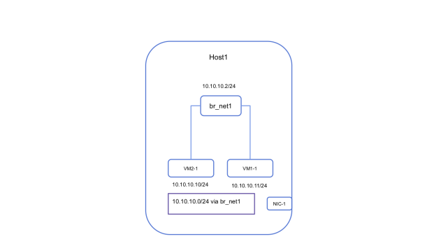
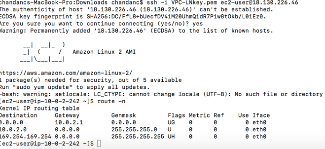
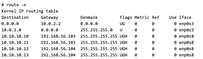
The following is the state of the routing table on the host after adding the bridge IP.

SS1

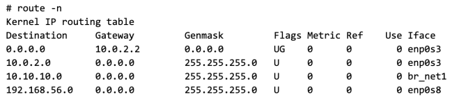
Note: I have 2 network interface on the Host (this is not necessary for the proposed network design, but just the way my Host is setup)

  • enp0s3 connects to internet
  • enp0s8 connects to the private lan, this is what I will use to connect the hosts

Connecting VMs on multiple Hosts

The above procedure can be replicated on other Hosts to start VMs and connect them locally. The only constraint here is that VM IPs should not conflict with each other.

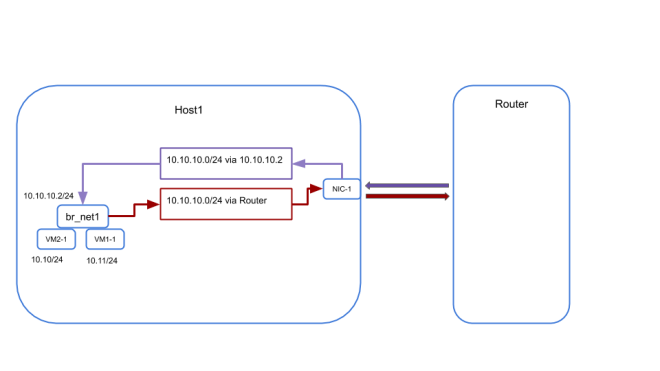
For explanation, let’s say that we have started the following VMs on two different hosts on a network called net1 with associated subnet 10.10.10.0/24

Host Name Host IP VM Name VM IP
Host1 192.168.56.103 VM1 10.10.10.10/24
VM2 10.10.10.11/24
Host2 192.168.56.104 VM3 10.10.10.12/24
VM4 10.10.10.13/24
Router 192.168.56.101

The bridge on each of the host are called br_net1 and is given an ip of 10.10.10.2/24(yes I am configuring the same IP on bridge on all the Hosts)

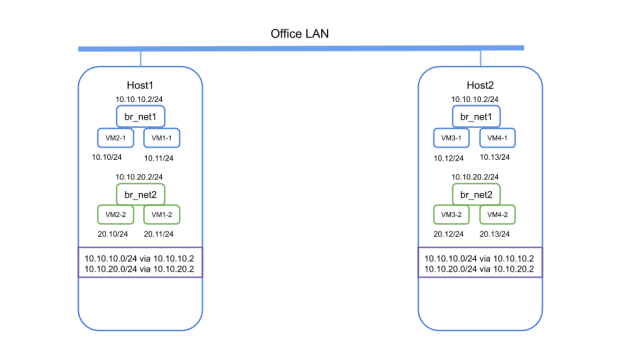
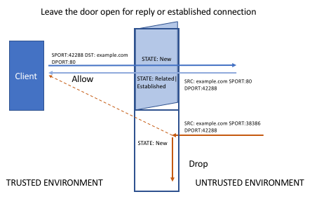
Now from the VM1 if we try to ping VM3 on Host2 it will fail as the bridge on Host1 has no knowledge of the MAC of VM3 as they are on two different L2 segments.

Resolving MAC address of remote VMs

To resolve the above situation I enabled proxy arp on the bridge. Please see my previous post for other examples where i used the same solution.

echo 1 > /proc/sys/net/ipv4/conf/br_net1/proxy_arp

This will allow the bridge to respond with its own MAC when an ARP query made by any connected VM and the destination IP is not known to the bridge.

SS2.png

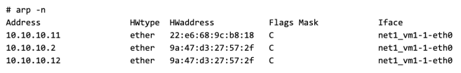
In this example you can see that the MAC of VM3 (10.10.10.12) is same as that of the bridge(10.10.10.2)

Sending Packet to a remote VM

Once the Bridge responds to the ARP query, VM1 will send the ping packet to the bridge. The kernel on the Host1 now has to decide the where to route the packet for VM3 by doing a route lookup. Linux by default will not forward packets across directly connected networks. To enable this behavior we need to enable ip_forwarding on the Host.

echo 1 > /proc/sys/net/ipv4/ip_forward

Now if we can make sure that the correct route exists on Host1 to reach VM3, we will be able to complete half of the round trip for the ping packet.

Introducing the Router (just another Linux Machine)

To resolve the routing problem we introduce another component in to the picture, which is a router. The router is connected to the same LAN to which the Host1 and Host2 are connected and its IP is 192.168.56.101(mentioned in the table above).

Although we can eliminate the need for a router by programming the routes on the Hosts, that approach will need managing a distributed routing table configuration across hosts. Using a central router makes managing configuration simpler.

The router is programmed with the correct destination for each of the VM using host routes. Here is an example of the routing table on the Router.

SS3.png

If we can send the packet destined to VM3 to this router, the router forward it to Host2(192.168.56.104) which we know in turn can forward it to VM3.

But first we have to solve another problem with routing.

Recalling from the previous illustration the routing table on the Host1 already has a route entry for net1 (10.10.10.0/24)

SS4.png

This is because the br_net1 interface is already configured with the ip of 10.10.10.2/24 and the linux kernel know that host1 is directly connected to net1. If we remove this route or the IP on the bridge the host cannot forward packets to the VMs connected to the bridge. With this route present we cannot forward packets on 10.10.10.0/24 to the router.

We will have the same configuration in the routing table of Host2 as Host2 is configured exactly the same way as Host1.

Resolving the Multiple route problem

To resolve this issue we will use policy based routing provided by linux kernel. You can get details of policy routing on linux in my previous post. In short policy based routing helps in route selection based on the attributes of the packet. In this case we will use the ingress port of the packet to decide which route to select for the packet.

Policy routing is enabled in two steps.

  • Create an alternate routing table which will hold the custom routing rules
  • Create a policy routing rule to select which table to use based on the properties of the packet

First we will create a separate routing table. The new routing table is identified by a routing table id (101) and name (sdn_net)

echo "101 sdn_net" >> /etc/iproute2/rt_tables

This table is configured with the following routes

ip route add 10.10.10.0/24 via 192.168.56.101 table sdn_net
ip route add default via 192.168.56.101 table sdn_net

To view the route entries in the table use the following command

SS5.png

Now we will add routing rule to select the correct routing table when forwarding traffic. The routing rule is based on the follow condition

  • if a packet enters the Host1 through the bridge br_net1 it must be trying to reach an IP not available on the VMs directly connected to the bridge. All such packets must be forwarded to the router and and so must use the new routing table we created.
  • While if the packet enters the Host through of its other network interfaces it might be destined for the VMs and they can continue to use the main routing table as usual.

Use the following command to create the rule

# ip rule add iif br_net1 lookup sdn_net

VLAN-5

Once the new routing table and the policy routing rules are applied to both the hosts the ping packet can complete its complete path and you should have connectivity between VMs across Hosts

Running multiple virtual networks and routing between them

With the previous step we achieved connectivity between VMs on the same network, but how do we enable VMs on one network to communicate to VMs one another network?

To do this we need to have a gateway configured for each of the virtual networks.

  • The VMs must be configured to use this gateway as the default route.
  • Default route must be added to the alternate route table we created
  • The gateway IP itself must be configured on the loopback interface on the router as a /32 address.

Once this is done for both the virtual network, VMs in one network can reach the VM on other.

Connecting to the internet

If you are creating network with subnets carved out of your office network (i.e. the IPs are routable in your office/home network you can make an route entry on your main router to forward all traffic for your virtual networks to the router we configured above and you should have internet connectivity.

But if you are running isolated virtual networks and the companies router does not have any configuration for your network. In that case you will need to apply NAT for all traffic going out of your virtual network.

A simple and manageable way to do this is to use iptables rule in conjunction with ipsets. To do this, create an ipset on the router as follows.

ipset create sdn_net hash:net

Add any network that needs Internet access to this ipset

ipset -A sdn_net 10.10.10.0/24

Following iptables rule can used to provide internet access.

iptables -t nat -A POSTROUTING -m set --match-set sdn_net src -j MASQUERADE

While using ipsets there is no need to change the iptables rule whenever a new virtual network is added or removed. Instead you can just update the ipset with the correct network list and iptables will pick it up.

Summary

Here is a quick summary how the virtual network works

  • All VM on a network on a Host connect to a bridge
  • All VMs and the bridge get an IP from the subnet associated with the network
  • This creates a routing entry in the main routing table of the Host and makes the virtual network directly connected to the Host
  • We enable proxy arping on the bridge to respond to any unanswered ARP query. This will be used to respond to the ARP queries for VMs hosted on remote hosts.
  • We enable IP forwarding to make sure packet reaching the bridge due to proxy arping can be forwarded to other networks
  • We add a router to the topology to forward traffic between VM on different Hosts and configure it with host routes for VMs
  • Finally we solve the different routes for ingress and egress packets from the bridge using policy based routing rules and alternate routing table.

Trying it out

While it is possible to test this solution by setting up your own lab. I have written a python program to automat the test setup. To try it out you will need 3 test machine connected to the same LAN(Host1, Host2 and Router). These machines can be VM. I used network namespaces to simulate the VMs that are launched on Host1 and Host2. The script can run from any machine but needs SSH Key based access to the root account of the 3 Hosts.   The code can be found here

Conclusion

So what are the advantage of using this network.

  • Ease of deployment, no need to manage VLANs, configuring switches
  • Ease of debugging, as all the features that we used are part of the linux kernel and mostly are layer 3 we can use regular debugging tools like ping, traceroute, tcpdump to debug the setup
  • Easily extensible, as we are not constrained by subnetting, no of tunnels etc. we can scale the solution horizontally
  • No ARP beyond the Host, any unanswered ARP queries originating in the VM are responded by the bridge. So your office switch never sees the ARPs from the VMs and the VM macs don’t overflow the mac tables of the physical switch
  • As we are dealing with L3 packets we can use VRRP or ECMP for providing HA and Load Balancing

System Monitoring: Glances at Top

System monitoring is one of the topics that has got a lot of attention lately.

A lot of options already exists in the open but every-time I search a for a system monitoring tool I am presented with options suitable for large scale cluster of machines, capturing metrics over time, showing trends of resource utilization over time and requiring a storage system and moderate to heavy installation. These systems are good for Ops teams interested in managing the stable operation of systems and optimization of resource utilization over time.

My requirements on the other hand are more on the side of debugging and require a real time peak in to the monitored system. To be frank my favourite tool for the job has been to use top command on the system to look at the current status of the system and it still one of the invaluable tools linux provides. It provides info on the load average, ram utilization and per process metrics with various selection and sorting options.

My requirements

More than often I start with a couple of physical machines and start by running virtual machines on them. A quick and easy monitoring tool is what I need to debug. Till now I would have a tmux session with windows running top command over ssh to these physical machines. I am mostly interested in the status VMs (kvm processes) running on the system and the overall health of the hypervisor.

One problem with top is it does not cover the network and disk metrics (which are a good to have feature), but most importantly although top provides the per process stats but I could not find a way to get alerts when a process (KVM instance in my case) starts to go high on resources.

Glances a better top

I recently tried glances and was really impressed with its capability. The most important part is the easy installation steps. Although I created a virtual environment and installed the app within it, it is not a requirement. To install glances all you need to do is to install the python package using pip and that’s it, you are ready to go

pip install glances

It has the same look and feel as top (although not as may selection and sorting option) but what it provides is a complete view of the system in real time including disk and network stats.

Screenshot 2019-04-15 at 8.20.51 AM

In addition you can define process level alerts for resource utilization.

It can act as standalone, client and a server mode. In the standalone mode it can monitor the status of the local system.

Screenshot 2019-04-15 at 8.17.38 AM

While in the server mode (with the -s option) it can be sending statistics to a remote client.

Or you can run it in the web server mode to monitor the system over a web browser(make sure you have bottle install for the webserver mode to work).

glances -w
Glances Web User Interface started on http://0.0.0.0:61208/

In the client mode you can create a list of servers that you need to monitor and start the client in the browse mode (with –browse option). The client will present you with a list of monitored server with a summary of their status. You can connect to any of them to get the detailed view.

Screenshot 2019-04-15 at 8.26.48 AM

The client connected to a remote server has the same look and feel as a standalone glances instance

My current installation

I am monitoring three physical machines with glances. I have glances running in the server mode on the physical machines and also in the web server mode (Currently you need to run 2 instances of Glances if you need both server and web server mode, there is a open request to enable both modes on the same instance of Glances)

I have installed glances in a virtual environment to keep its dependencies separated for the rest of the system.

I am running it under supervisord to make sure we have the process always running and restarted after reboot.

No surprise performance test

Recently I had a need to deploy some python FLASK based application. Although FLASK has a convenience CLI built-in to run your application while developing the deployment documentation provided a bunch of production ready deployment method. After going through the various documentation and learning about the event loop based implementation of Gevent, I decided to try out Gevent based deployment and wanted to compare its performance with the default flask CLI. I used the simplest of Flask app (hello world) to try it out.

And no surprise that the Gevent based deployment came out to be better than the default flask cli, but the difference in performance is seen only when the number of request and concurrency was really high. I used Apache bench to test the performance. A total of one hundred thousand requests were served by the application and at a concurrency level of one hundred

ab -c100 -n100000 http://localhost:8181/

And just for completeness I also tried similar application written in Golang as Go also uses event loops with its goroutine. The final comparison was made with Nginx which is also an event loop based web server (it looks very unfair to compare app server with static file, but the app was very simple and it returns just a string). Nginx served the exact same content as the apps did.

Overall Nginx was the winner as expected followed by Go App, python3.x asyncio based aiohttp,  python Gevent and finally the Flask App cli. What I liked about the experiment is it gave me a perspective of how much of a performance difference we can expect while choosing our tools and how to compare it against the development time and effort.

Time per request(mean) in ms

You can see the code and results here

Test Driving transmission for multi-site file sync

As the industry moves towards more distributed deployment of services, syncing files across multiple location is a problem that often needs to be solved. In the world of file synching there are two algorithms that are outstanding. One being rsync which is a very efficient tool for synching files. It works great when you have a few remotes that need to be kept in synch, but as soon as the number of remotes grow we hit the problem of bandwidth and load. Rsync being a single-source-to-destination syncing mechanism, puts a lot of load on the source as the source node needs to transfer a lot of data to each of the remotes. 

filesync (1)

This is the use case where sync based on bittorrent protocol shines. As bittorrent uses peer-to-peer file distribution there is no single source that distributes the files. Files are broken down into chunks and each chunk is associated with its hash. To get a copy of the file a participating peer asks for all the chunks of the file from all other peers. Any peer that has the chunk can be the source for this transfer. Additionally the file chunks are not transferred sequentially, but the transfer is randomized to make sure that possibility of finding the requested chunk in any other peer (rather than the original source) increases.     

filesync

In this blog I will explore all the components needed to set up a bittorrent based file sync. A lot of these steps can be automated to come up with an efficient multi-site file synching solution. All the setup is done on a single Ubuntu 16.04 VM. Following diagram shows my test setup.

filesync

How to use a bittorrent network to share your data ?

To transfer your data using torrents you will need the following things

  • The full copy of the source files that you want to transfer
  • Torrent file generated for the source files
  • Some way to distribute this torrent file to all your remotes (peers)
  • A torrent tracking server
  • A torrent client

Installing transmission client

Although you can use any torrent client, transmission is one of the popular torrent client for linux. It provides a CLI (and RPC API) interface which is handy for integration with other projects.

To install transmission on your machine use the following command

apt-get install transmission-cli transmission-common transmission-daemon transmission-gtk transmission-remote-gtk 

This should get transmission installed. To configure the torrent client edit the settings file

/etc/transmission-daemon/settings.json 

You might be interested to change the default download directory which by default points to

/var/lib/transmission-daemon/downloads/

Make sure that transmission has write access to the new download directory you set.

Transmission uses systemd unit to manage the transmission client daemon. If you want to make changes to transmission daemon follow the standard practice of customizing any systemd service. For my experiment I disabled authentication for RPC calls. To do this follow the steps as below.

cp /lib/systemd/system/transmission-daemon.service     /etc/systemd/system/transmission-daemon.service 

Then edit the system file in /etc/systemd/system/<service> with your local changes

diff -Nur /etc/systemd/system/transmission-daemon.service /lib/systemd/system/transmission-daemon.service 
--- /etc/systemd/system/transmission-daemon.service 2019-03-15 22:30:59.736229363 +0530
+++ /lib/systemd/system/transmission-daemon.service 2018-02-06 23:25:40.000000000 +0530
@@ -5,7 +5,7 @@
 [Service]
 User=debian-transmission
 Type=notify
-ExecStart=/usr/bin/transmission-daemon -f --log-error -T
+ExecStart=/usr/bin/transmission-daemon -f --log-error
 ExecStop=/bin/kill -s STOP $MAINPID
 ExecReload=/bin/kill -s HUP $MAINPID

Start the transmission daemon as follows

systemctl start transmission-daemon

And check its status with the following command

systemctl status transmission-daemon

Next step is to create a torrent file for your source files. Before you can create a torrent file you need to provide a tracker url. The next section will show you how to setup your own tracker server or you may choose to use public tracker server

What is a torrent tracker ?

A torrent tracker is a server which tracks all the peers that are interested in a torrent file distribution. It also helps peers interested in a file transfer to find each other. When a torrent client adds a new torrent file, it looks for the track url embedded in the torrent file and contacts the tracker server and gets a list or other peers that are interested and participating in the source file distribution. The client can then contact all its peers and start requesting chunks of the source file.

You can either use a public torrent tracker server, but if you are using torrents to share private data probably you will want to use a private torrent tracker server. For my experiment I tried

https://github.com/chihaya/chihaya.git

To setup the tracker use the following steps at https://github.com/chihaya/chihaya/blob/master/README.md

You will need to install Golang for compiling it. Once compiled you should have a binary named chihaya in your sources top dir. An example configuration file is provided as part of the code example_config.yaml

cp example_config.yaml config.yaml

Then edit it to your liking. As I am running this experiment on my local machine, I changed the http addr to “127.0.0.1:6969”

http:
    addr: "127.0.0.1:6969"

In a real deployment your tracker should be accessible from all the peers, so it must listen on a public interface. The default setting is to listen on “0.0.0.0:6969”.

Once done start the tracker server as follows

./chihaya --config config.yaml 

This will start the server and your tracker url will be http://127.0.0.1:6969/announce or the IP you configured for the http listen address.

How to create a torrent ?

To create the  torrent file use the following command.

transmission-create <source file|source dir> -t <tracker url>

For me

transmission-create <source file|source dir> -t http://127.0.0.1:6969/announce

The above command will create the torrent file for your source file(s). The torrent file will contain the chunks definition of the source file along with its hash and the tracker url. Each time a new peer adds the torrent file. The torrent client will send a request to the tracker to add itself to the list of peers interested in the source file.

How to publish your files with torrent ?

To publishing the source file you need to add its torrent (like we created in the steps above). The only difference between all the other peers and the publisher is that the publisher will be the peer with the complete source file to start with. The peers with the complete files are also known as seeders while all the peers who have incomplete source files are called leechers. In the beginning the publisher will be the only seeder but as more and more peers get a complete source file they will also become seeders.

To add a torrent file and become a seeder use the following command.

 transmission-remote --add <torrent file> -w <parent dir of complete source files> [ -u <upload bandwidth limit in kb/s>]

The upload bandwidth limit is optional.

How to download files ?

This should be the the most familiar part to everyone. Although for this blog we will use the transmission client for the reasons mentioned above. All the peers need to add the torrent file we created above to the transmission client. The torrent file can be hosted on a web server or can be sent to the peers over mail or any other means.  To add a torrent file to all other peers use the following command

transmission-remote --add <torrent file> -w <parent dir where the source file will be saved> [ -u <upload bandwidth limit in kb/s>]

You can use the following commands to list the currently added torrents in transmission

transmission-remote -l
transmission-remote -t <torrent_id> -r

Where torrent_id is the first column in the output of transmission-remote -l. You can also use the web or gtk interface if you like to use transmission

http://localhost:9091/transmission

Or run transmission-gtk to use the GUI

Once you have added the torrent with the transmission-remote –add <torrent file> -w <parent dir where the source file will be saved> command, transmission with verify that the available source file matches the hash in the torrent file.

Once completed your transmission client will be marked as a seeder. For my test I used another torrent client to download the source files by using the torrent file.

In production you would like to use the transmission-remote on the peers to add the torrent file and start the download.

Summary

If you have the need to distribute files among multiple remotes, torrents can be a very efficient mechanism. You can relieve the source file server of the synching load and also benefit from better bandwidth utilization of the peers, not to mention the increased speed of distribution

Extending my Private LAN behind NAT to AWS

WordPress on EC2 with DB in private LAN

We have all known and talked about a hybrid cloud solution to spill over an On-Prem infrastructure to cloud providers like AWS. Recently I had a need to do (a POC that needed) the same for my private lab where part of my software runs on the cloud while still communicating with the in house components.

The standard solution for this is to setup a VPN connection between your private lab and AWS. Only  problem is that I don’t have a public IP available to setup the tunnels and also I am behind the ISPs NAT. So the VPN solution does not work for my case.

Hence I used SSH to setup the poor mans version of VPN tunnels.

The setup in detail

Basic idea is that you have a pair of tunnel host setup on the VPC and your private lab as seen in the figure below and use the tunnel to route traffic between the networks.

Tunnel

Setting it up

Following steps will bring up the setup.

  • First start the pair of tunnel host one on the the Private LAN (TH1) another on VPC with a Public IP (TH2). These hosts will act as the tunnel gateway. I used Ubuntu based VMs for the tunnel hosts.

In our case the tunnel host on the private LAN will act as SSH client to initiate the tunnel connection.

  • Update the SSH configuration file /etc/ssh/sshd_config on the server side (TH2) to allow creation of tunnels. 
PermitTunnel yes

Note: SSH sessions are terminated if there are no activity for a certain amount of time. I found some help full suggestion to keep the connection alive, you can also read about it the sshd_config man page. Here is the gist of it

Update your SSH server (TH2) configuration with the following options

ClientAliveInterval 120
ClientAliveCountMax 720

Update Client (TH1) config  ~/.ssh/ssh_config with the following

ServerAliveInterval 120
  • Next setup the tunnels using SSH connections.

As the tunnels are setup using SSH connection so  having a Public IP (TH2_Public_IP) on the AWS side is enough.  Client side can reside behind the ISP provided NAT with no need of public IP. SSH connections are setup as root user.

 On the client(TH1):
     # ssh -i AWS_SSH_KEY.pem -f -w 0:0 <TH2_Public_IP> true
     # ifconfig tun0 1.1.1.10 netmask 255.255.255.0 up

     tun10
Similarly setup the tunnel host on AWS 

On the server(TH2):
    # ifconfig tun0 1.1.1.20 netmask 255.255.255.0 up
  • Check if you tunnel connection is up by pinging the tunnel IPs (1.1.1.10 and 1.1.1.20 from each other).
  • Next setup routing on the tunnel hosts to connect the private lab to your VPC.
On the client(TH1):
# route add 172.31.0.0/20 1.1.1.20

On the server(TH2):
# route add 192.168.56.0/24 1.1.1.10

Here is the route table on the TH2 after update

route20.png

  • Then setup routes on the EC2 instances to redirect traffic to your tunnel host(TH2) on AWS using its Private IP (TH2_Private_IP) (can be automated using Systems manager).

On each EC2 instance on the VPC

# route add 192.168.56.0/24 <TH2_Private_IP>

Same changes updates needs to be done on the private LAN instances using the Private ip of the local tunnel host(TH1_Private_IP)

# route add 172.31.0.0/20 <TH1_Private_IP>

Although you can also update the route on the LANs gateway if you have access to if you don’t want to every individual host on your LAN.

Test application: WordPress on EC2 with DB in private LAN

To test my setup I ran a WordPress server on the AWS while my DB remained on my local LAN. 

You will have to make MySQL/MariaDB listen to the all IPs on the machine, open up firewall rules to allow MySQL access on port 3306 and setup a db user and database with proper privileges.

mysql.png
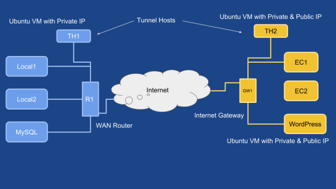
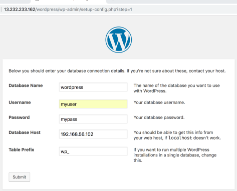
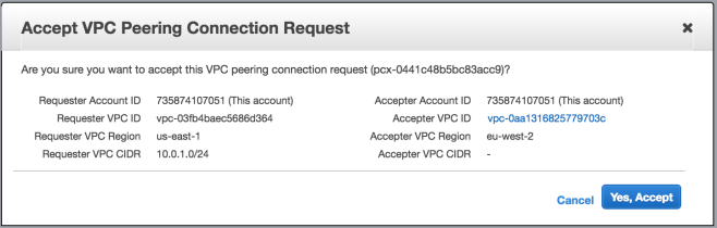
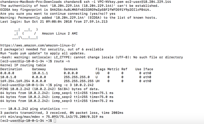
Once done start an EC2 instance (I used ubuntu 18 image) on the VPC and make sure that you can connect to MySQL on the private LAN.

Also make sure that you add SecurityGroup rules to provide access to HTTP port for WordPress

wordpress4.png

Install WordPress on this host along with php and a web server (used Nginx). You should be able to use the private LAN IP of the MySQL server and complete the install.

wordpress5

and ons installed you should be able to use the WordPress app as usual.

wordpress12

Conclusion

This is definitely not a production type of setup. I set this up for my personal need to experiment. The tunnel depends on liveness of SSH connection, although we have increased the timeout the connection may drop if there is no communication beyond the timeout period.

Test Driving Inter Regional VPC peering in AWS

Connect AWS VPCs hosted in different regions.

AWS Virtual Private Cloud(VPC) provides a way to isolate a tenant’s cloud infrastructure. To a tenant a VPCs provide a view of his own virtual infrastructure in the cloud that is completely isolated, has its own compute, storage, network connectivity, security settings etc.

In the physical world, Amazon’s data centers are organized into different geographical location called Regions. Each Regions has multiple Availability Zones which are data centers with independent power and connectivity to protect against any natural disaster.
A VPC is associated with a single Region. A VPC may have multiple associated subnets (one per Availability Zone). Subnets in VPC do not span across Availability Zones.

What is VPC Peering ?

Although as an AWS tenant, VPCs provide you with a secure way to isolate and control access to your cloud resources; it also creates its own challenges. As your infrastructure grows, you are forced to create multiple VPCs within or across multiple Regions. Question is: How would you now connect your instances deployed in different VPCs?

One way to connect your resources across VPCs is over the Public IP. This meant the traffic has to traverse the internet to travel between your cloud resources hosted in different regions.

Peering provides a solution to this problem by allowing instances in different VPCs to connect over a peering link. Till recently VPC peering was only allowed within a single region. This was before AWS allowed creating VPC Peering across Regions. With Inter Regional VPC peering the traffic between instances in VPC in different regions never have to leave the Amazon network.

Note: One thing to keep in mind while peering VPCs is that the peered VPCs should not have overlapping subnets CIDRs. As VPC peering involves route table updates to add routes to remote subnets, any CIDR overlap between the local and remote subnet will not work.

Creating Inter Regional VPC peering

To test Inter Regional VPC peering, you will need to create two custom VPCs in different Regions. I have explored custom VPC and Internet access in my previous post. For this test I am peering custom VPCs created in N. Virginia (CIDR 10.0.1.0/24) and London (CIDR 10.0.2.0/24) Region.

The peering links can be created in the “VPC” dashboard under the “Networking & Content Delivery” heading. To create a peering link navigate to

Networking & Content Delivery > VPC > VPC Peering Connections and click on the Create peering Connection.

VPC10

To create a peering connection you must know the VPC id of the local and peer VPC in the remote Region. While the local VPC can be chosen for the drop down menu, you must find the remote VPC id from the remote Region’s VPC console. On completing the above step a VPC peering request is created with status as pending

VPC11

To activate the peering link, the VPC in the remote Region must accept the peering request.

VPC13

Click “Accept Request” and “Yes, Accept”

VPC14

Once accepted the status of the peering link changes to Active.

VPC16

The next step is to update the route table of your VPC and add a route to the subnets associated with your peered VPC using the VPC peering link interface which are named as pcx-xxxxx…

Note: The route table must be updated on both the local and remote VPC to provide a complete forward and reverse path for the traffic.

VPC17

And that’s all. Now you should be able to communicate between the peered VPCs. You can try running ping or SSH between the instances on the VPCs. You may have to adjust the Security group rules to make this work.

VPC18

No transitive routing with VPC peering and problem of manual route table update

One of the limitation of VPC peering is that it only allows communication across directly connected VPCs.[As of Oct 2018]

As an example if VPC-A peers with VPC-B and VPC-B peers with VPC-C, the traffic is only allow between VPC-A , VPC-B and VPC-B, VPC-C. The peering link is not transitive this means VPC-A cannot send or receive traffic from VPC-C. To enable this VPC-A must directly peer with VPC-C.

VPC22

This means multiple VPCs wanting to communicate with each other in the group must form a full mesh of peering links. Additionally the route table associated with each of the VPC needs to be manually updated with the subnet CIDRs of all its peers and correct peering link. This can be quite tricky to maintain with manual updates.

Although third party routing solutions can be used to enable transitive routing, but it will undermine the routing infrastructure provided by AWS.

Recent Updates

AWS now supports accessing load balancers over Inter Regional Peering Links

https://aws.amazon.com/about-aws/whats-new/2018/10/network-load-balancer-now-supports-inter-region-vpc-peering/

Custom VPC and Internet Access in AWS

Create your VPC, launch EC2 instances and get internet access with Public IP.

With a Virtual Private Cloud(VPC), tenants can create his own cloud based infrastructure in AWS. While AWS provides a default VPC for a new tenant, there are always use cases that need creation of custom VPC.

While exploring custom VPC, I found that getting the my EC2 instances on the custom VPC to connect to the internet was not a straight forward and involves a few steps.

The next sections describe the steps needed to make the EC2 instances get internet access with Public IP

1. Creating the Custom VPC and associated Subnet

To create a custom VPC navigate to Networking & Content Delivery > VPC > VPCs  and click on “Create VPC” and provide a name for your custom VPC and an associated CIDR.

VPC1

VPCs are tied to your logged in Region. If you have multiple Availability Zones in this region you may want to create one Subnet per Availability Zone but further sub-netting the CIRD associated with the VPC. In my case I have created only one Subnet for the custom VPC.

VPC2

2. Creating an Internet Gateway for the custom VPC

Next step is to create an internet gateway. The internet gateway connects the VPC to the internet. To create it navigate to Networking & Content Delivery > VPC > Internet Gateways and click on “Create internet gateway

VPC4
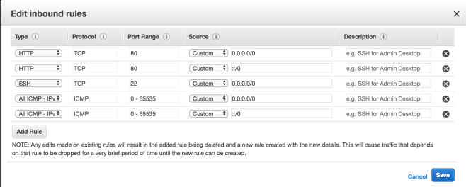
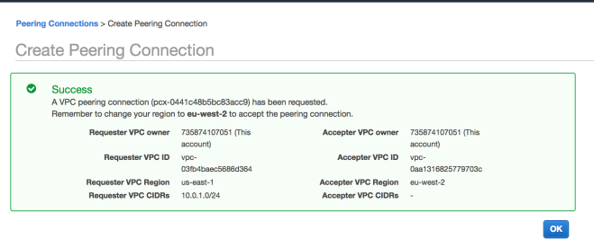
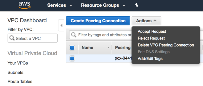
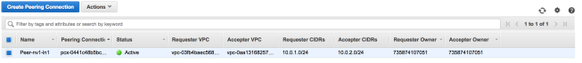
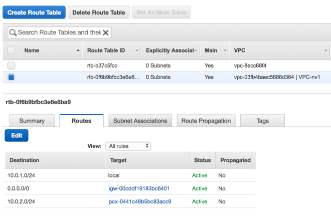
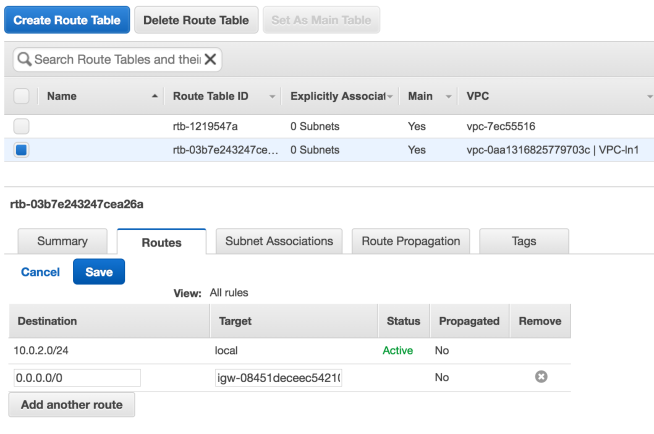
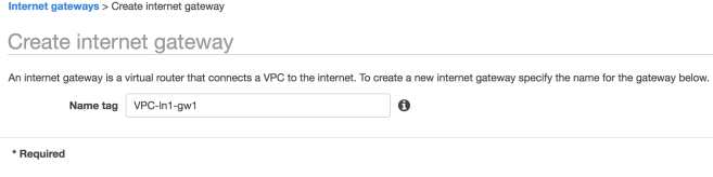
Next associate this Internet Gateway to your Custom VPC using the Actions menu after selecting the newly created Internet Gateway. After this step the Gateway should have an associated VPC

VPC6

3. Update Routing Table for the VPC to allow traffic to and from Internet

Next we have to update the routing table to add a default route to send and receive traffic from internet.

To do this navigate to Networking & Content Delivery > VPC > Route Table and select the routing table associate with the custom VPC and click on the “Routes” tab then click on edit and add a default route. Next click “Save” to update the routing table.VPC7

4. Launching EC2 instances on the custom VPC and checking connectivity

Finally we are ready to launch our EC2 instance and make it internet accessible using Public IP.

To do this navigate to Compute > EC2 and click on “Launch Instance

Follow the usual steps to Launch the instance except in the “Configure Instance” stage select your custom VPC for the network(this will automatically load the associated Subnet) and enable Auto-assign Public IP.VPC21
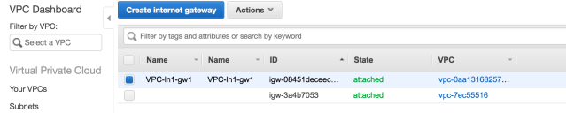
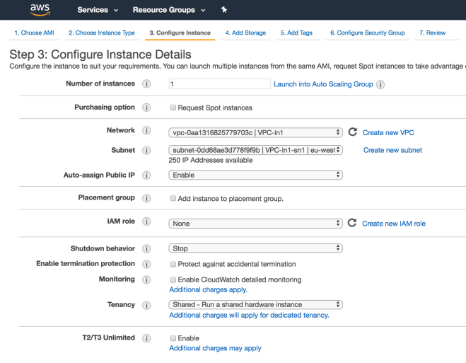
You will be asked to create a new Security Group for the VPC (allow SSH access for testing).

Once launched you should be able to SSH to the instance using its Public IP.

VPC9


Stateful vs Stateless firewalls: Which one to use when?

Firewalls provide traffic filtering and protects the trusted environment for the untrusted. A firewall can be stateful or stateless

A stateful firewall is capable of tracking connection states, it is better equipped to allow or deny traffic based on such knowledge.  A TCP connection for example goes through the handshake (SYN-SYN+ACK-ACK), to EASTABLISHED state, and finally is CLOSED. A stateful firewall can detect these states.  If a packet belongs to an already running flow it can be allowed, while a new connection form the untrusted host can be dropped.

Let’s take a scenario to understand this better

A client sitting behind firewall connects to a web server www.example.com. and receives a reply.

Let’s see what configuration of the stateful and stateless firewall are needed to make this communication work.

Stateful Firewall configuration:

# Generic rule to allow clients to connect to any
# webserver on the internet
Allow traffic going out to port  80
Allow traffic related to connections initiated by any internal client back to the same client
Deny any other traffic coming in to the client

Stateless Firewall configuration:

Allow traffic going out to port  80 on www.example.com
Allow traffic coming from host www.example.com and port 80
Deny any other traffic coming in to the client

From the above it is clear that the stateful firewall will allow incoming traffic only if it is related to connections the client has started. Also, note that this makes it possible to write generic rules for a stateful firewall.


Slide1

Stateless firewall on the other hand does not have any knowledge of what connections the client has initiated, instead it depends purely on the attributes of the packet like source, destination address etc. to make the allow or deny decision.

Why do we need stateless Firewalls?

Stateful firewall needs to track each of the connection that passes though the firewall. It needs to maintain the state of all the active connection. New connections are actively added and expired connection are purged from the connection state maintained by the firewall. This requires a lot of resources (memory, cpu) on the firewall and as such is a costly.

Another consideration is load balancing traffic on multiple firewalls. In case of stateful firewall the connection state must be synchronized across multiple firewalls to provide a consistent view of active connections.

A stateless firewall on the other hand deals with a single packet at a time. Thus, the resources needed by such a filtering process is much less.

When to use Stateless firewall?

A stateless firewall can be a faster and less resource intensive alternative in the following cases

  • Server side firewall: If you are running a purely server application with well-known ports on a machine. In this case firewall can be explicitly programmed to allow connection to and from the server port. As the server ports are well known to the firewall and the server expects new connection anyway, stateless firewalls can handle this use case.
  • Client side firewall: A client program which strictly connect to a small set of trusted hosts (internal) can be protected using stateless firewalls with specific rules.

A stateful firewall on the other hand can be used to protect client applications which connect to a large number of untrusted hosts (webservers on internet, peer-to-peer traffic).  The connection tracker on the stateful firewall will only allow incoming packets which are related to communications started by the internal clients. All new traffic trying to reach the client application will be dropped by the stateful firewall.

Home network traffic analysis with a Raspberry Pi 3 and Ntop

I had the Raspberry Pi laying around for some time without doing any major function and so was the NetGear switch [1]. So, I decided to do a weekend project to implement traffic analysis on my home network.

I have a PPPoE connection to my ISP that connects to my home router [2]. The router provides both wire and wifi connectivity. As with most people I have very few devices that connect to the router over an Ethernet cable, most devices are wifi capable. This makes traffic monitoring a bit of a problem on the LAN side.

To get around the problem I decided to put the traffic monitor on the WAN side of the router.

The following figure shows the connectivity.

Slide1

Tapping the WAN side with port mirroring

The NetGear GS105E switch provides the capability of port mirroring. I used this to mirror traffic arriving through the router and the ISP connection. The mirrored traffic is passed on to the Raspberry Pi. All traffic monitoring happens on the Pi.

Screenshot from 2018-02-11 01:26:51

Monitoring tools

Once the traffic is available on the mirrored port, I was able to run traffic monitors like wireshark, tshark and tcpdump on the mirror port to analyze all the traffic between the router and ISP. These tools give a live view of the packets going through my home network.

To monitor traffic over long time I used Ntop [3]. It can aggregate and produce nice traffic analysis summary. I used the Rasbian [4] image for the pi and Ntopng can be easily installed from their repository using apt.

Accessing the Monitoring result

As the Gigabit port of the Pi is used to receive mirrored traffic, the monitoring dashboard is accessed over the wlan0 interface. This will keep the monitored traffic separate from the monitoring traffic.

ntop


Adding NtopNG to Grafana

Now the monitoring data from ntopng can can be exported to Grafana. A detailed process can be found at

https://www.ntop.org/ntopng/ntopng-grafana-integration-the-beauty-of-data-visualizazion/

Ntop can even be run from a docker container

https://hub.docker.com/r/ntop/ntopng


Refs:

[1] https://www.netgear.com/support/product/GS105Ev2.aspx

[2] https://www.amazon.in/3G-4G-LTE-Router-Multi-WAN/dp/B00N0W4FTM

[3] https://www.ntop.org/products/traffic-analysis/ntop/

[4] https://www.raspberrypi.org/downloads/raspbian/